First, go to the Add Bus button on the toolbar,
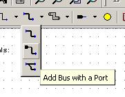 , and click the arrow just to the
right. Select the Bus with Port option. Now make sure the
Add Bus button is highlighted, or selected, if not left-click
on it to do so. Now when you move the mouse over the design area
you will see the pointer is now a crosshair. Left-click once with the
left button near the left hand side of the design area to begin drawing
a bus. If you move the pointer you will see the outline of an input port
with a bus extending out of it to the point where the pointer currently is.
Move the pointer to the right six or seven grid spaces and double-click
with the left button to terminate the bus with a dangling net connector,
which will be represented by an open circle at the end of the bus. The left
hand side of the bus should have an input port attached to it and the right
hand side should end in an open circle, meaning it is not yet connected to
anything. Also a default name, dbus0, has been assigned to the
bus with a default type unsigned(15 DOWNTO 0) and this has
been added to the Declarations list.
, and click the arrow just to the
right. Select the Bus with Port option. Now make sure the
Add Bus button is highlighted, or selected, if not left-click
on it to do so. Now when you move the mouse over the design area
you will see the pointer is now a crosshair. Left-click once with the
left button near the left hand side of the design area to begin drawing
a bus. If you move the pointer you will see the outline of an input port
with a bus extending out of it to the point where the pointer currently is.
Move the pointer to the right six or seven grid spaces and double-click
with the left button to terminate the bus with a dangling net connector,
which will be represented by an open circle at the end of the bus. The left
hand side of the bus should have an input port attached to it and the right
hand side should end in an open circle, meaning it is not yet connected to
anything. Also a default name, dbus0, has been assigned to the
bus with a default type unsigned(15 DOWNTO 0) and this has
been added to the Declarations list.
By default, the Add Bus button will remain active until you press the Escape key or click with the right mouse button or on another button on the toolbar. While it remains active, add three more busses to the diagram below the first one so that it looks something like Figure 2. Space your ports and busses at least two to three grid spaces apart.
You may move the bus around on the block diagram by making sure that
the selection tool,  , is active and then
pressing and holding the left mouse button over a point in the middle of
the bus and dragging it to the new position. You should see the outline
of the bus as you drag and reposition it. You may make the bus longer
or shorter at this point by pressing and holding the left mouse button
over the dangling net connector circle and dragging it to the new location.
, is active and then
pressing and holding the left mouse button over a point in the middle of
the bus and dragging it to the new position. You should see the outline
of the bus as you drag and reposition it. You may make the bus longer
or shorter at this point by pressing and holding the left mouse button
over the dangling net connector circle and dragging it to the new location.
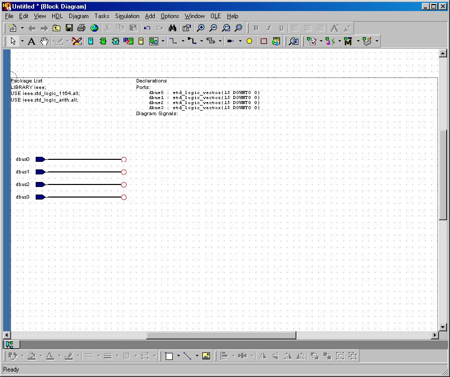
Figure 2
Add an input signal in the same way you added buses. Click on the Add Signal
button on the toolbar,  , and click the arrow just to
the right. Select the Add Signal with a port option. Add the signal input so
that your design looks something like Figure 3. This input signal will be used for
SHAMT_HIGH.
, and click the arrow just to
the right. Select the Add Signal with a port option. Add the signal input so
that your design looks something like Figure 3. This input signal will be used for
SHAMT_HIGH.
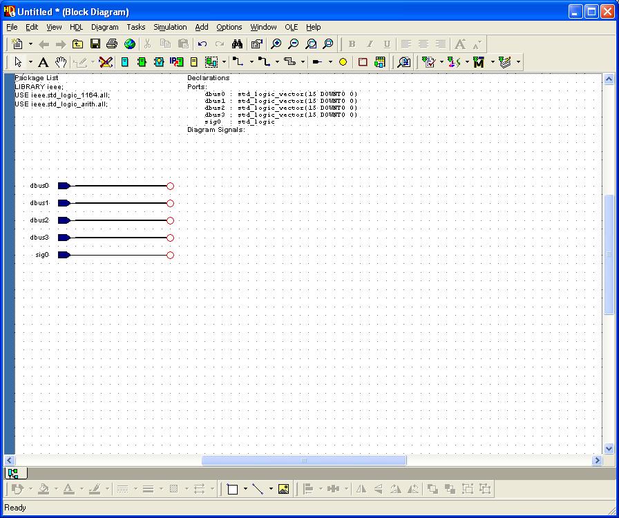
Figure 3
The Add Bus button, unfortunately, cannot be used to add an output port in the manner described above. Before adding the output ports, resize the design area so that it extends almost the width of the screen. This way we can add output ports at the far right and have plenty of room in between to place the blocks which will give the ALU its functionality.
In order to add an output port click on the Add Port Out button:
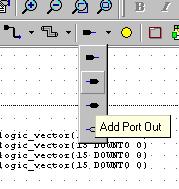 . Now move the pointer to the right hand
side of the design area and place an output port in the design. While
the tool is still active, place two more output ports, making sure to
leave at least two vertical grid dots between each port.
. Now move the pointer to the right hand
side of the design area and place an output port in the design. While
the tool is still active, place two more output ports, making sure to
leave at least two vertical grid dots between each port.
Now change the Add Bus button back to Bus Without Port.
Move the pointer to the design area and left-click on the hanging
end of output port. Move the mouse about six or seven grid spaces
to the left and double-left-click to terminate the bus with a dangling
net connector. For the other two output ports, follow the same procedure,
except using the Add Signal button, ,
set to Signal Without Port. The Add Signal button is used
because two of the outputs, Zero and Overflow, are single
bit signals instead of multi-bit busses. Your Design should now look like
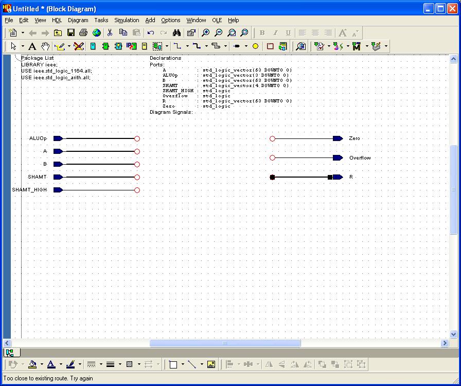
Figure 4.
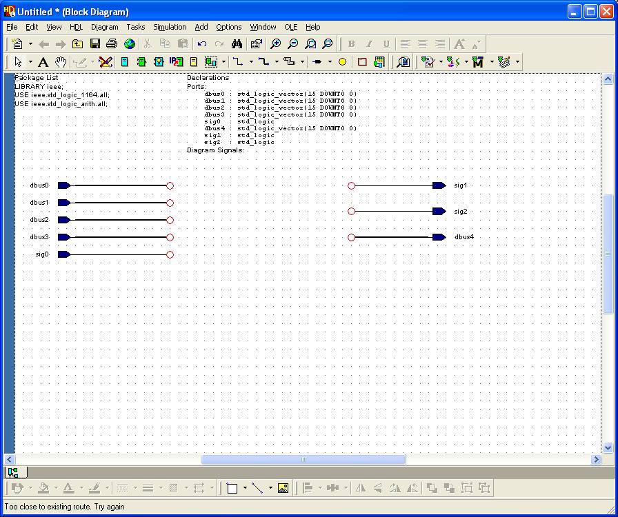
Figure 4
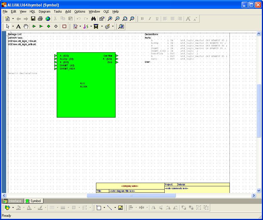
Since we do not want to use the default names for the signals and
busses, we need to assign our own. To do this, first make sure
that the selection tool, , is active
and then double-left-click on the bus dbus0. This will
bring up the Object Properties window opened to the signals
tab with the dbus0 signal selected. In the name field
replace dbus0 with ALUOp. In the declaration section,
set the bounds as 3 DOWNTO 0.
Finally click OK. These changes should be reflected on the signal
name and the Declarations.
Change the rest of the signals and busses as shown in the following table. The design should now resemble Figure 5.
| Original Name | New Name | New Type | New Range |
| dbus0 | ALUOp | std_logic_vector | 3 DOWNTO 0 |
| dbus1 | A | std_logic_vector | 63 DOWNTO 0 |
| dbus2 | B | std_logic_vector | 63 DOWNTO 0 |
| dbus3 | SHAMT | std_logic_vector | 4 DOWNTO 0 |
| dbus4 | R | std_logic_vector | 63 DOWNTO 0 |
| sig0 | SHAMT_HIGH | std_logic | NONE |
| sig1 | Zero | std_logic | NONE |
| sig2 | Overflow | std_logic | NONE |
 .
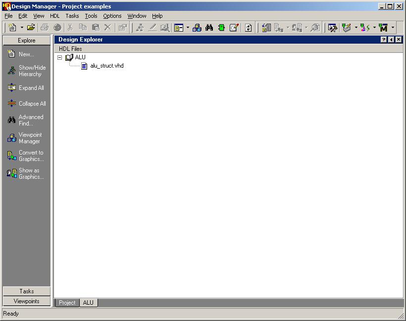
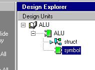
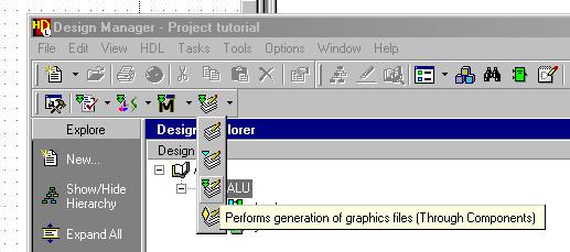
Left-click on the plus sign to expand
the tree under ALU and you should see an entry for ALU_struct.vhd as in
Figure 8. Double-left-click on this file to open it up in a
VHDL editor.
.
Left-click on the plus sign to expand
the tree under ALU and you should see an entry for ALU_struct.vhd as in
Figure 8. Double-left-click on this file to open it up in a
VHDL editor.